Q138 / 150 · MHT CET 2026 (15 April Shift 2) · Physics
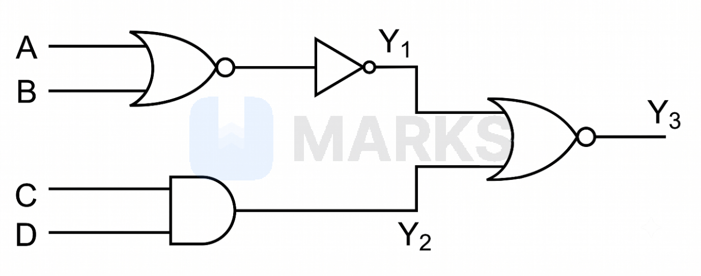
In the logic circuit diagram, when all the four inputs, A, B, C, D are 'one' the outputs $Y_1$, $Y_2$, $Y_3$ are respectively (1, 1, 0). When the inputs A and C are changed to zero and B and D are still 'one', then the outputs $Y_1$, $Y_2$, $Y_3$ are respectively change to
- A$1, 1, 1$
- Correct answerB$1, 0, 0$
- C$0, 1, 0$
- D$0, 0, 1$
Solution
From the given logic circuit diagram, we can determine the Boolean expressions for the outputs $Y_1$, $Y_2$, and $Y_3$.
The output $Y_1$ is the result of a NOR gate with inputs $A$ and $B$, followed by a NOT gate:
$Y_1 = \overline{\overline{A + B}} = A + B$
The output $Y_2$ is the result of an AND gate with inputs $C$ and $D$:
$Y_2 = C \cdot D$
The output $Y_3$ is the result of a NOR gate with inputs $Y_1$ and $Y_2$:
$Y_3 = \overline{Y_1 + Y_2}$
Given the new input conditions: $A = 0$, $B = 1$, $C = 0$, and $D = 1$.
Substituting these values into the expressions:
$Y_1 = 0 + 1 = 1$
$Y_2 = 0 \cdot 1 = 0$
$Y_3 = \overline{1 + 0} = \overline{1} = 0$
Therefore, the outputs $Y_1$, $Y_2$, and $Y_3$ are $1, 0, 0$ respectively.
Answer: $1, 0, 0$
Hence, the correct answer is option: 'B'.