Q69 / 150 · MHT CET 2025 (26 Apr Shift 1) · Mathematics
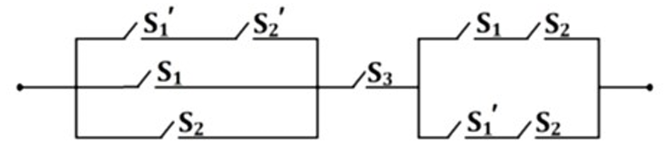
Consider statements $\mathrm{p}: \mathrm{S}_1$ is closed; $\mathrm{q}: \mathrm{S}_2$ is closed; $\mathrm{r}: \mathrm{S}_3$ is closed. The simplified equivalent circuit diagram and its logical statement for the switching circuit is respectively.
- A
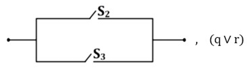
- B
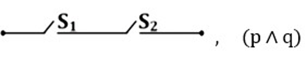
- Correct answerC

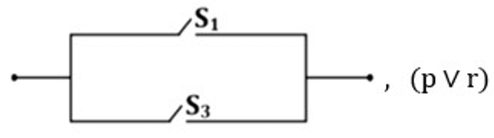
- D
Solution
Translating the switching circuit into logical expressions, let $p$ represent $S_1$ closed, $q$ represent $S_2$ closed, and $r$ represent $S_3$ closed.
The leftmost parallel block contains three branches: $\neg p \wedge \neg q$, $p$, and $q$. The disjunction $(\neg p \wedge \neg q) \vee p \vee q$ simplifies to $\neg(p \vee q) \vee (p \vee q)$, which is always true. This block is equivalent to a closed switch.
The middle component is switch $S_3$, represented by $r$.
The rightmost parallel block has branches $p \wedge q$ and $\neg p \wedge q$. Their disjunction $(p \wedge q) \vee (\neg p \wedge q)$ factors as $q \wedge (p \vee \neg p)$, simplifying to $q$.
The entire circuit in series gives $T \wedge r \wedge q = q \wedge r$, meaning $S_2$ and $S_3$ in series.
Comparing with the options, only option C shows $S_2$ series $S_3$ with logical statement $q \wedge r$.
Hence, the correct answer is option: 'C'.