Q55 / 57 · KVPY 2019 (SA) · Physics
A student uses the resistance of a known resistor ( ) to calibrate a voltmeter and an ammeter using the circuits shown below. The student measures the ratio of the voltage to current to be in circuit
(a) and in circuit (b). From these measurements, the resistance (in ) of the voltmeter and ammeter are found to be close to
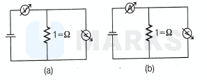
A student uses the resistance of a known resistor ( ) to calibrate a voltmeter and an ammeter using the circuits shown below. The student measures the ratio of the voltage to current to be in circuit
(a) and in circuit (b). From these measurements, the resistance (in ) of the voltmeter and ammeter are found to be close to
- Aand
- Correct answerBand
- Cand
- Dand
Solution
When a voltmeter put in series, it still reads potential drop and when an ammeter is connected in parallel, it still shows current through it.
Case a
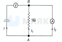
Let current through cell, then potential drop read by voltmeter is (this is reading of voltmeter) Where, is the resistance of voltmeter In loop, and
Where, is the resistance of ammeter We substitute for from above equation to get
(this is reading of ammeter)
Now given,
1000$
Case b
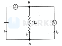
Let current through cell, then ammeter reading in this case is I.
Also, in loop A B,
As,
So,
Hence, voltmeter reading is (this is reading of voltmeter)
Now given, voltmeter reading ammeter reading
Substituting in Eq (i), we get
or
Hence, the correct answer is option: 'B'.